Showing posts with label ferroequinology. Show all posts

Monday, February 21, 2011

Ferroequinology: More Running Boards

Saturday, I revisited SERM to spend some time on A&WP 290. The previous visit, we cleared several brackets and attached steam and air pipes to expose a nearly clear boiler shell. In preparation for Ultrasonic Thickness testing, a grid over each course of the shell must be arranged and test points ground to expose bare metal. To access the entire shell, running boards on the fireman's (left) side of the locomotive needed to be installed.

Installing the fireman's side running boards used all of the mounting hardware remaining and, to our chagrin, exposed mistakes in mounting the engineer's side running boards. This image depicts the two large castings that support both running boards and compressed air tanks. Each of the four castings is distinct, not correctly labeled, and not easily positioned even with a crane (of which I have become a precise and efficient operator).

Engineer's side running boards on A&WP 290 installed on Jan 15, 2011 at Southeastern Railroad Museum. Pictured: AWP290 project manager Dale Grice.

Ultimately, we had to remove the engineer's side running boards, remove what we guessed was the incorrectly placed bracket, place a different bracket, reinstall the running board, install that bracket on the other side in both possible locations, and hopefully achieve the best fit. Moreover, studs can be bent so it's a matter of luck and judgment to determine whether a part doesn't fit because it's not the correct part or because you're not using a large enough hammer.

By end of day, with many possible combinations attempted, all air tank brackets were soundly mounted, running boards placed, and the boiler now accessible from all sides. During the next disassembly, we'll surely stamp each casting and avoid confusion in the future... ha.

Up next, ultrasonic thickness measurement over every square foot of a 37ft pressure vessel with working pressure 201 psi and operational temperature of 450 degF.

Tuesday, January 18, 2011

Ferroequinology: Running Boards

We hoisted engineer's side running boards onto the brackets mounted the previous week. Now, it is possible to access the top of A&WP 290's boiler shell. We used the opportunity to heat and remove a handful of brackets to clear several sand and steam pipes.

Protip: when applying a socket wrench to a red-hot steel nut, make sure your gloves are dry to prevent any unwanted heat transfer...

Update: water soaked into gloves acts as a thermal conductor resulting in scalds if a gloved hand is applied to steel whose temperature is several hundred degrees above the boiling point of water.

Sunday, January 9, 2011

Ferroequinology: clearing A&WP 290's Boiler Shell

Yesterday, I visited the Southeastern Railway Museum and worked on A&WP 290 with Dale Grice.

In continuing with the goal of removing everything from the boiler shell to prepare for an eventual blast with baking soda, we removed a steam pipe carrying a "signal" that actuates cylinder cocks. A valve in the engineer's side of the cab raises steam pressure in this pipe which actuates valves at the bottoms of the main cylinders at the front of the locomotive that permit condensation and steam to blow out when the locomotive starts. This is why steam engines seem to start in a cloud of steam.

A&WP 290 venting cylinder cocks

This required removing two unions coupling a network of steel pipes. I tried without luck during a previous visit to wrench them apart. Yesterday, we used a "rosebud" oxy-acetylene torch to heat the union coupling to dull cherry red then quenched it with a cup of water. The first coupling I tried this on came loose readily and after one revolution with the wrench [and plenty of time to cool], I removed it the rest of the way with torque applied by [gloved] hand.

The second union would not budge in spite of this treatment. Between heatings, I hit it with a hammer but it remained fast. Consequently, we used a cutting torch which emits a jet of oxygen gas through a flame and oxidizes steel. A short segment of pipe was cut between the union and a T-coupling thus freeing the main pipe along the boiler.

With unions apart, the cylinder cock pipe would come loose with the removal of a single bracket fastened to the boiler shell via a threaded stud. Unfortunately, the nut holding the bracket was corroded and could not be made to turn without heat. After heating to cherry red, a wrench with torque magnified by a breaker bar [steel pipe] eventually made some progress. Or we thought it was progress. After about half a revolution the nut fell off revealing we had literally torqued the 1/2" stud apart and never moved the nut. One more thing to fix on the boiler...

I manned the portable crane and we pulled the pipes off the boiler then applied a set of labels so they can be replaced or new copies made.

To reach the top of the boiler, the next step was to replace air cylinder brackets. These are large castings [weighing probably 50 or 60 pounds each] that suspend two large air cylinders along the locomotive, one on each side, and support running boards.

A&WP 290 in New Georgia Railroad's Pullman Yard

Again, I manned the crane lifting the castings up to the boiler while Dale aligned them with 1.5" diameter threaded studs. These studs were placed in the boiler from within when it was built and cannot be easily replaced without potentially compromising the boiler's integrity [not to mention incurring a laborious and detailed inspection]. The first bracket went on without much trouble but we discovered it was mis-labeled and didn't sit flush with the boiler shell. The next bracket didn't slide onto the studs at all, and we discovered the reason was due to the forward stud bent up and forward. The studs needed to be parallel for the bracket to slide on, and this clearly wouldn't do.

To straighten it, Dale fitted a large 12' steel pipe over the stud, and I climbed up on a scaffold. The plan was for me to bend the stud using the pipe as a lever. Doing this proved problematic; the pipe was not adequately stiff, and all force I applied deformed the pipe like a spring. I had visions of losing my grip and the pipe springing back; the last thing I would see is a 2.5" steel pipe swinging back to hit me in the face...

We abandoned this idea pretty quickly. When Dale attached a nut to the end of the stud and hit it with a sledgehammer without any success, he decided heat was the only solution. Again, the rosebud torch came out and in no time, the base of the stud was glowing cherry red. Each gentle stroke of the sledgehammer moved the end of it by about 1/4", and in no time we had straightened it.

Both brackets slid on without difficulty after this, and now we'll be able to add running boards and access the top of the boiler. Progress!

Saturday, March 6, 2010

Baker Valve Gear Simulator in Python

What started off as a compile-time project has finally yielded some results.

As some of you are aware, my interests in engineering exceed computing and from time to time take the front seat for brief periods. In this case, I've spent two weekends volunteering at the Southeastern Railway Museum shops with the hope of working on the preservation and restoration of the exquisite A&WP 290. The neat thing about steam locomotives is they're incredibly overt exhibitions of thermodynamics and mechanics. The boiler is a giant heat exchanger that sends steam to cylinders where work is performed. A mechanical linkage outside the frame transmits this power to the wheels and uses the wheel position to configure valves that admit and exhaust the working fluid.

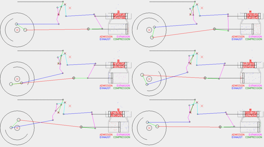
One of the things I was interested in was a mathematical model of this linkage. This sort of modelling has applications in robotics and kinematics simulations, so it's not too bizarre of a topic for a computer engineer to dabble in. To simulate the valve gear, I constructed a set of polynomial equations modelling each rod as a constant length between two points capable of 2D motion in a plane. The collection of pin joints and rigid rods determines a finite set of possible static equilibria for the system. Enough points can be computed analytically so a numerical non-linear equation solver can compute the others.

I wrote a Python application [distributed as source] using SciPy's fsolve() to simulate the running gear. Plots generated with matplotlib provide visual output.

Here are some of the results. This wikipedia article explains the Baker valve gear and this animated gif shows it in operation [generated from an existing valve gear simulator which I've not yet used to validate mine]. Other valve gears are explained on this page if you're interested.

The following plot illustrates the state of the running gear for several wheel rotations. Not every part is a two-joint rod; there is a bellcrank and an eccentric crank mounted to the main crank pin. See the Wikipedia article for a better illustration.


Baker valve gear simulation


The following plot illustrates the offsets of the crosshead and cylinder valves for two different cutoffs and two different laps. Cutoff is the angle between vertical and the valve gear's yoke. 0 degrees is effectively neutral, and +25 degrees is "well forward." Setting it to a negative angle reverses the locomotive. Lap is, in a manner of speaking, the amount of motion derived from the crosshead; the valves can move this much without actually admitting any steam. It's worth noting that lap is built into the valve gear, while cutoff is a setting that is adjusted during operation.


Baker valve gear simulator - cylinder valves


To achieve smooth operation, it's desirable to admit steam into the cylinder before the piston has reached front or back dead center. This "lead" is effectively a phase offset that depends on the direction of motion. The amount of lap affects the amount of lead by mixing the 90-degree offset motion of the valve gear with the crosshead via the combination lever. The following plot illustrates the displacement of the cylinder valves as zero-mean curves to enable a direct comparison of 0" and 3.5" of lap. In practice, it's easy to add a constant linear offset to the cylinder valve spindle, and this is one of the variables that must be tuned when the locomotive is overhauled.


zero-mean cylinder valve displacement


The rod sizes and geometry used in this simulation were estimated from photographs of A&WP 290 as well as direct measurements. I didn't get every measurement I wanted, as I was taking them by hand with a tape measure that falls apart, and real locomotives are 3 dimensional and quite large. Nevertheless, this was an interesting project and I'm very gratified by the results. Maybe one day I'll build a 7.5" gauge live steamer and dust off this code for design purposes...

Monday, December 28, 2009

Southeastern Railway Museum

The day after Christmas, my parents, Emma, and I spent the afternoon at the Southeastern Railway Museum. Their large and growing collection includes a number of cosmetically restored rolling stock from railroads in the Southeast including several large steam locomotives. This post covers some of the photographs from that visit.

S&A #750
Savannah and Atlant #750 - This 4-6-2 "Light Pacific" built in 1910 pulled excursions all around the Southeastern U.S. including one in 1989 that I rode on. It was last operated that year and currently sits on static display, having been cosmetically restored.